The UDP Reporter is essentially designed for machine to machine applications via Ethernet. Connections can be made either over a local network or a wide area network.
On a local network the UDP reporter can be addressed using either a fixed IP address or using a Netbios name. The latter allows the use of obtaining an address automatically using DHCP.
Using a wide area network either a fixed wide area address can be used or the UDP Reporter can use a Dynamic DNS server if your gateway supports such functionality.
Operation of the UDP Reported requires that a link is established between it and the remote machine. The link may be established by either end and can be programmed using the interface application.
Once established each end will send periodic packets to the other end as a heartbeat thus allowing for corrective action if the link fails. If an output needs to be triggered the machine end can send an immediate packet which can be marked as urgent. Upon receiving this message the UDP Reporter will reply with a confirmation message which will show the new status.
Similarly if an input changes state the UDP Reporter will send a message marked urgent to the remote machine. If this message is not acknowledged within about 1 second it will be resent until an acknowledgment is received. This methology ensures that changes are reported with the minimum of delay.
Inputs can be individually defined as being active in either the open or closed condition which means that they can be controlled using either open or closed contacts. Similarly outputs can be defined as either active high or active low.
In addition the start up conditions outputs can be defined so that on power up all output will be in a known condition.
The UDP Reporter will also report on the current value of the analogue inputs with control of the value change need before an out of sequence report is generated.
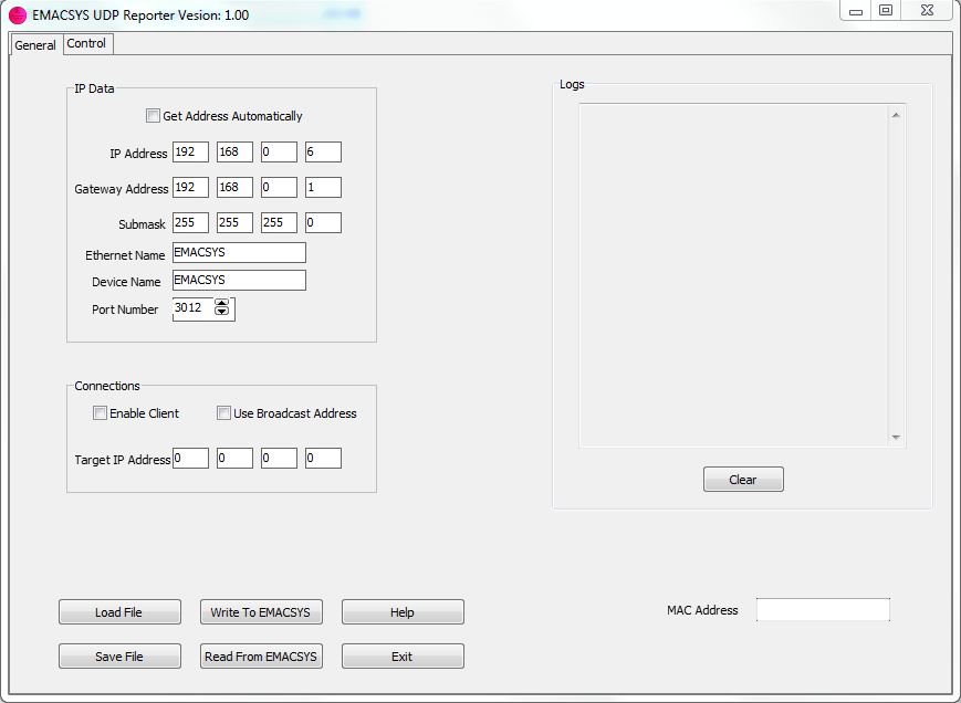
Main page of the UDP Reporter interface application showing the IP configuration data.
At the bottom of the page there are buttons for loading and saving the data and for loading and reading from EMACSYS via the USB port.
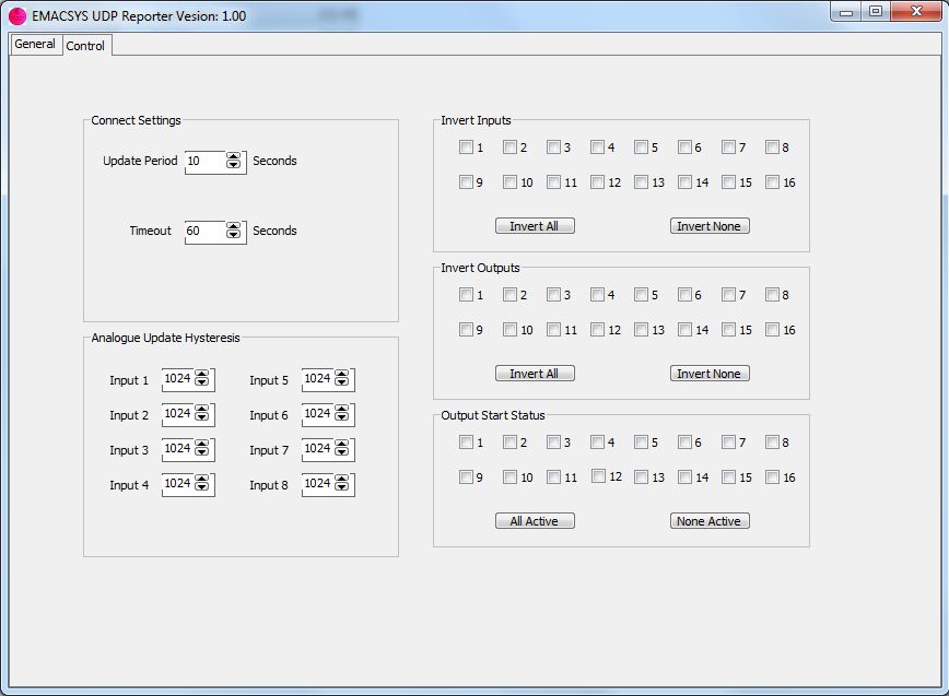
The top left of the page shows the link control values used to determine the frequency of messages and how long to wait before the firmware decides that the link is down.
Below that is the hysteresis panel which determines how much an input needs to change before sending an out of sequence message.
To the right input and output active polarity is defined together with the output start status.
For most applications you will probably need to write you own application. However there is a demonstration application on the Applications page.
The protocol allows for the controlling of outputs by setting their state to either active or inactive, by toggling the output of by pulsing the output. The latter command allows for setting the pulse period in steps of 10mS.
Hardware requirements:
EMACSYS control module.
EMACSYS Ethernet module.
I/O as required.